2017年1月23日星期一

Levitating Smartphones? New Magnetic Charger Makes It Happen


Okay. There are dozens of new cell phone chargers that have come out in the last few years that do everything from disinfect your phone to shut down the charging process once your phone is topped up (if you haven’t unplugged it yet). They also come in all shapes and sizes now, including one that’s roughly the size of a credit card. But, there’s a new smartphone charger that’s trying to work its way into the hearts and minds of the public that comes with a nifty trick we’d normally associate with somebody like Criss Angel or David Copperfield: it makes your phone levitate.
The OvRcharge

Yes, these masters of illusion aren’t the only ones with magic up their sleeves. It’s called the OvRcharge, and it’s a wireless charger than can levitate your smartphone using magnets instead of slight of hand or distraction. My first thought when I heard about this was aren’t magnets supposed to be bad for computers? I thought you could wipe your memory that way. Apparently, that’s not a legitimate concern (so much for my knowledge of electronics). The thing is, though, that this charger looks really cool when it’s in use. At first glance, it appears to be a small, polished block of wood that might serve as a stand for some type of knickknack or a trophy pedestal. Nope.

Kickstarter

If you’re someone who has to have the latest gadget or gizmo and/or are big on novelty items, this might be something for you. The OvRcharge is currently making a bid for backing on Kickstarter, where the group behind it hopes to have it out and available to the public by an estimated December 2016 release date. So far, AR Designs has received roughly half of the financial backing needed to fulfill orders and begin shipping. They’re based out of Toronto, Canada. If they aren’t able to reach their funding goal of $40,000 CAD by August 18 of 2016, you can probably forget about getting one this year.

Cell Phone Chargers

In order for this “wireless” charger to work, users of the product have to slip their phone inside a thin case that comes with the base unit. The case actually looks like the kind you’d buy to protect your phone, but less clunky and clumsy. The special case consists of two main parts: an electrical induction receiver and a magnet for holding your phone aloft. As far as cases, AR Designs says, “We offer most popular model's cases but it is not possible at the moment to carry all types of cases, in this case we are offering third party attachment to work with your own case and supplied magnet (so generally speaking it works with all kind of phones or most of em).”

Charging Base

The attractive charging base comes in two sizes and three colors choices. The only difference between the two models, besides a slight difference in size, is the output current rate: the smaller is 500mAh and the larger offers 700 mAh. Both models are said to be fully compatible with all of their cases and receivers. The unit is powerful enough to levitate 600 grams and charge it, so tablets aren’t a problem. You can order the bases in stains that include dark, walnut and cherry. If you’re interested in learning more about how the OvRcharge works and costs associated with it, check out their Kickstarter page for all the details.


2017年1月19日星期四

Learn Electronics With These 10 Simple Steps

Do you want to learn electronics, so that you can build your own gadgets?
There is a ton of resources on learning electronics – so where do you start?
And what do you actually need?
And in which order?
If you don’t know what you need to learn, you can easily waste a lot of time learning unnecessary things.
And if you skip some of the simple but crucial first steps, you’ll struggle with even the basic circuits for a long time.
If your goal is to be able to build your own ideas with electronics, then this checklist is for you.
When you follow the checklist below, you will get up to speed fast – even if you have no experience from before.
While some of these steps might take you a weekend to tackle, others can be done in less than an hour – if you find the right teaching material.
Start by reading through all the steps all the way to the end to get an overview.
Next, decide what teaching material you will use to tackle each step.
Then start to learn electronics.
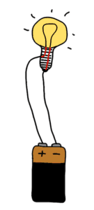
Step 1: Learn the Closed Loop
If you don’t know what is needed for a circuit to work, how can you build circuits?
The very first thing to learn is the closed loop.
It’s essential to make a circuit work.

After finishing this step you should know how to make a simple circuit work. And you should be able fix one of the most common mistakes in a circuit – a missing connection.
This is simple, but necessary knowledge to have when learning electronics.
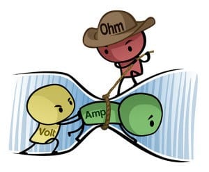
Step 2: Get a Basic Understanding of Voltage, Current and Resistance
Current flows, resistance resists, voltage pushes.
And they all affect each other.
This is important to know to learn electronics properly.
Understand how they work in a circuit and you will have this step nailed.
But, there’s no need to dive deep into Ohm’s law – this step can be learned through simple cartoons.

After finishing this step, you should be able to look at a very simple circuit and understand how the current flows and how the voltage is divided among the components.
Step 3: Learn Electronics By Building Circuits From Circuit Diagrams
No need to wait no more – you should start building circuits now. Not just because it’s fun, but also because this is what you want to learn to do well.
If you want to learn to swim, you have to practice swimming. It’s the same with electronics.

After finishing this step you should know how circuit diagrams work and how to use a breadboard to build circuits from them.
You can find free circuit diagrams for almost anything online – radios, MP3 players, garage openers – and now you’ll be in a position to build them!
Step 4: Get a Basic Understanding of These Components
The most common components you’ll see in the beginning when learning electronics are:
  • The resistor
  • The LED
  • The capacitor
  • The transistor
You can get a basic understanding of each of these quickly, as long as you have good learning materials. 
But take note of that last statement “as long as you have good learning material” – because there is a lot of terrible learning material out there.
After completing this step you should know how these components work and what they do in a circuit.
You should be able to look at a simple circuit diagram and think:
“Aha, this circuit does this!”.
Step 5: Get Experience Using the Transistor as a Switch
The transistor is the most important single component in electronics.
In the previous step you got an intro to how it works. Now it’s time to use it.

Build several different circuits where the transistor acts as a switch. Like the LDR circuit.
After completing this step you should know how to control things like motors, buzzers or lights with the transistor.
And you should know how you can use the transistor to sense things like temperature or light.
Step 6: Learn How To Solder
Prototypes built on a breadboard are easy and quick to build. But they don’t look good and the connections can easily fall out.
If you want to build gadgets that look good and last for a long time, you need to solder.

Soldering is fun, and it’s easy to learn.
After completing this step you should know how to make a good solder joint – so that you can create your own devices that look good and will last for a long time.
Step 7: Learn How Diodes and Capacitors Behave in a Circuit
At this point you will have a good foundation of the basics, and you can build circuits.
But your efforts to learn electronics should not stop here.
Now it’s time to learn to see how more complicated circuits work.
After completing this step – if you see a circuit diagram with a resistor, a capacitor and a diode connected in some way – you should be able to see what will happen with the voltages and currents when you connect the battery, so that you can understand what the circuit does.
Note: If you can also understand how the Astable Multivibrator works, then you’ve come a long way. But don’t worry too much about it, most explanations of this circuit are terrible.
Step 8: Build Circuits Using Integrated Circuits
Up until now you’ve been using single components to build some fun and simple circuits. But you’re still limited to the very basic functions.
How can you add cool functionality to your projects, like sound, memory, intelligence and more?
Then you need to learn to use Integrated Circuits (ICs).
These circuits can look very complex and difficult, but it’s not that hard once you learn the right way to use them. And it will open up a whole new world for you!
After completing this step you should know the steps for using any integrated circuit.
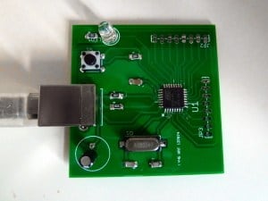
Step 9: Design Your Own Circuit Board
At this point you should have built quite a few circuits.
And you may find yourself a bit limited because some of the circuits you want to build requires a lot of connections.
To learn electronics properly, you should definitely do this step.
Now is the time to learn how to create your own circuit boards!
You can start with a simple program such as Fritzing to get started. If that is not sufficient for your needs, learn a more advanced PCB design software such as Eagle or KiCad.
After completing this step you should know how to design a PCB on a computer, and how to order cheap PCB prototypes of your design online.
Step 10: Learn To Use Microcontrollers In Your Projects
With integrated circuits and your own custom PCB design you can do a lot.
But still, if you want to really be free to build whatever you want, you need to learn to use microcontrollers. It will really take your projects to the next level.
Learn to use a microcontroller, and you can create advanced functionality with a few lines of codes instead of using a huge circuit of components to do the same.

After finishing this step you should know how to use a microcontroller in a project, and you will know where to find information to learn more.
adobe-pdf-iconDo you want this step-by-step checklist in PDF format to see the exact steps I recommend to learn electronics from scratch?
Click here to download the checklist now >>
Need Help With Any of the Steps?
With this checklist you can learn electronics on your own. You are free to find your own learning material from anywhere you want.
You can find information in books, articles and courses to help you on your journey.
I recommend finding someone who has a teaching style that you enjoy – and avoid those that teaches in ways you don’t enjoy.

2017年1月16日星期一

Hack-proof RFID chips could secure credit cards, key cards, and pallets of goods

Researchers at MIT and Texas Instruments have developed a new type of radio frequency identification (RFID) chip that is virtually impossible to hack.

If such chips were widely adopted, it could mean that an identity thief couldn't steal your credit card number or key card information by sitting next to you at a café, and high-tech burglars couldn't swipe expensive goods from a warehouse and replace them with dummy tags.
Texas Instruments has built several prototypes of the new , to the researchers' specifications, and in experiments the chips have behaved as expected. The researchers presented their research this week at the International Solid-State Circuits Conference, in San Francisco.
According to Chiraag Juvekar, a graduate student in electrical engineering at MIT and first author on the new paper, the chip is designed to prevent so-called side-channel attacks. Side-channel attacks analyze patterns of memory access or fluctuations in power usage when a device is performing a cryptographic operation, in order to extract its cryptographic key.
"The idea in a side-channel attack is that a given execution of the cryptographic algorithm only leaks a slight amount of information," Juvekar says. "So you need to execute the cryptographic algorithm with the same secret many, many times to get enough leakage to extract a complete secret."
One way to thwart side-channel attacks is to regularly change secret keys. In that case, the RFID chip would run a random-number generator that would spit out a new secret key after each transaction. A central server would run the same generator, and every time an RFID scanner queried the tag, it would relay the results to the server, to see if the current key was valid.
Blackout
Such a system would still, however, be vulnerable to a "power glitch" attack, in which the RFID chip's power would be repeatedly cut right before it changed its secret key. An attacker could then run the same side-channel attack thousands of times, with the same key. Power-glitch attacks have been used to circumvent limits on the number of incorrect password entries in password-protected devices, but RFID tags are particularly vulnerable to them, since they're charged by tag readers and have no onboard power supplies.
Two design innovations allow the MIT researchers' chip to thwart power-glitch attacks: One is an on-chip power supply whose connection to the chip circuitry would be virtually impossible to cut, and the other is a set of "nonvolatile" memory cells that can store whatever data the chip is working on when it begins to lose power.
For both of these features, the researchers—Juvekar; Anantha Chandrakasan, who is Juvekar's advisor and the Vannevar Bush Professor of Electrical Engineering and Computer Science; Hyung-Min Lee, who was a postdoc in Chandrakasan's group when the work was done and is now at IBM; and TI's Joyce Kwong, who did her master's degree and PhD with Chandrakasan—use a special type of material known as a ferroelectric crystals.
As a crystal, a ferroelectric material consists of molecules arranged into a regular three-dimensional lattice. In every cell of the lattice, positive and negative charges naturally separate, producing electrical polarization. The application of an electric field, however, can align the cells' polarization in either of two directions, which can represent the two possible values of a bit of information.
When the electric field is removed, the cells maintain their polarization. Texas Instruments and other chip manufacturers have been using ferroelectric materials to produce nonvolatile memory, or computer memory that retains data when it's powered off.
Complementary capacitors
A ferroelectric crystal can also be thought of as a capacitor, an electrical component that separates charges and is characterized by the voltage between its negative and positive poles. Texas Instruments' manufacturing process can produce ferroelectric cells with either of two voltages: 1.5 volts or 3.3 volts.
The researchers' new chip uses a bank of 3.3-volt capacitors as an on-chip energy source. But it also features 571 1.5-volt cells that are discretely integrated into the chip's circuitry. When the chip's power source—the external scanner—is removed, the chip taps the 3.3-volt capacitors and completes as many operations as it can, then stores the data it's working on in the 1.5-volt cells.
When power returns, before doing anything else the chip recharges the 3.3-volt capacitors, so that if it's interrupted again, it will have enough power to store data. Then it resumes its previous computation. If that computation was an update of the secret key, it will complete the update before responding to a query from the scanner. Power-glitch attacks won't work.
Because the chip has to charge capacitors and complete computations every time it powers on, it's somewhat slower than conventional RFID chips. But in tests, the researchers found that they could get readouts from their chips at a rate of 30 per second, which should be more than fast enough for most RFID applications.
"In the age of ubiquitous connectivity, security is one of the paramount challenges we face," says Ahmad Bahai, chief technology officer at Texas Instruments. "Because of this, Texas Instruments sponsored the authentication tag research at MIT that is being presented at ISSCC. We believe this research is an important step toward the goal of a robust, low-cost, low-power authentication protocol for the industrial Internet."

2017年1月11日星期三

Introduction of PIC18F4550 Microcontroller

PIC18F4550


PIC18F4550 belongs to pic18f family of microcontrollers. PIC18F4550 is one among the advanced Microcontrollers from the microchip technology. This microcontroller is very famous in between hobbyist and learners due it functionalities and features such as ADC and USB Integration. A typical PIC18F4550 comes in various packages like DIP, QPF and QPN. These packages can be selected according to the project requirement.

PIC18F are inexpensive and Easy to Program

Features


PIC18F4550 is an 8 bit microcontroller. PIC18F4550 has been implemented withNano WATT technology hence it requires very low power for its operation.


PIC18F4550 has 16 bit Instruction Set Architecture, (ISA) which provides a degree of freedom to programmers with various data types , registers ,  instructions, memory architecture, addressing modes, interrupt and IO operations. PIC18F4550 also has an Extended Instruction Set as a special feature; it’s an optional extension to the PIC18 instruction set.
Memory Specifications: A PIC18F4550 has 256 bytes of EEPROM (Electrically Erasable and Programmable Read Only Memory), 2KB of SRAM (Static RAM) and 32KB of flash memory which in return proves another degree of freedom to programmers.
Communication Protocol: PIC18F4550 is remarked as advanced, as it uses well sophisticated protocols for communications. The modern protocols like USB, SPI, EUSART, are well supported in PIC18F4550. These technologies integrate with Nano Watt Technology (as mentioned before) to produce PIC18F4550, a well equipped, low power consuming microcontroller. 
A Dedicated ICD/ICSP Port allows the programmers to code and debug easily.
  • Enhanced flash program and the 1KB Dual Access RAM for USB are used for buffering.
  • PIC18F4550 consists of up to 13 channels for analog to digital converter. The converter accuracy amounts to 10-bit to convert analog to digital signal relatively.
  • PIC18F4550 is compatible to work with different internal and external clock sources. It comes with four built-in timers or an external oscillator can be interfaced for clocking.
  • The frequency limit for a PIC18F4550 is from 31 KHz to 48 MHz respectively.
  • The microcontroller PIC18F4550 comes with ADC comparators and other such peripherals as an in-built feature.

A very good description and in detailed features of PIC18F4550 microcontroller can be found in its respective datasheet. A copy of that PIC18F4550 Datasheet can be downloaded from kynix’s website.

2017年1月9日星期一

Beyond silicon—the search for new semiconductors

Our modern world is based on semiconductors. In addition to your computer, cellphones and digital cameras, semiconductors are a critical component of a growing number of devices. Think of the high-efficiency LED lights you are putting in your house, along with everything with a lit display or control circuit: cars, refrigerators, ovens, coffee makers and more. You would be hard-pressed to find a modern device that uses electricity that does not have semiconductor circuits in it.

While most people have heard of silicon and Silicon Valley, they do not realize that this is just one example of a whole class of materials.
But the workhorse silicon – used in all manner of computers and electronic gadgets – has its technical limits, particularly as engineers look to use electronic devices for producing or processing light. The search for new semiconductors is on. Where will these materials innovations come from?
What's a semiconductor?
As the name suggests, semiconductors are materials that conduct electricity at some temperatures but not others – unlike most metals, which are conductive at any temperature, and insulators like glass, plastic and stone, which usually don't conduct electricity.
However, this is not their most important trait. When constructed properly, these materials can modify the electricity moving through them, including limiting the directions it flows and amplifying a signal.
The combination of these properties is the basis of diodes and transistors which make up all our modern gadgets. These circuit elements perform a multitude of tasks, including converting the electricity from your wall socket to something usable by the devices, and processing information in the form of zeros and ones.
Light can also be absorbed into semiconductors and turned into electrical current and voltage. The process works in reverse as well, allowing for the emission of light. Using this property, we make lasers, LED lights, digital cameras and many other devices.
The rise of silicon
While this all seems very modern, the original discoveries of semiconductors date back to the 1830s. By the 1880s, Alexander Graham Bell experimented with using selenium to transmit sound over a beam of light. Selenium was also used to make some of the first solar cells in the 1880s.
A key limitation was the inability to purify the elements being used. Tiny impurities – as small as one in a trillion, or 0.0000000001 percent – could fundamentally change the way a semiconductor behaved. As technology evolved to make purer materials, better semiconductors followed.
The first semiconducting transistor was made of germanium in 1948, but silicon quickly rose to become the dominant semiconductor material. Silicon is mechanically strong, relatively easy to purify, and has reasonable electrical properties.
It is also incredibly abundant: 28.2 percent of the Earth's crust is silicon. That makes it literally dirt cheap. This almost-perfect semiconductor worked well for making diodes and transistors and still is the basis of almost every computer chip out there. There was one problem: silicon is very inefficient at converting light into an electrical signal, or turning electricity back into light.
When the primary use of semiconductors was in computer processors connected by metal wires, this wasn't much of a problem. But, as we moved toward using semiconductors in solar panels, camera sensors and other light-related applications, this weakness of silicon became a real obstacle to progress.
Finding new semiconductors
The search for new semiconductors begins on the periodic table of the elements, a portion of which is in the figure at right.
In the column labeled IV, each element forms bonds by sharing four of its electrons with four neighbors. The strongest of these "group IV" elements bonds is for carbon (C), forming diamonds. Diamonds are good insulators (and transparent) because carbon holds on to these electrons so tightly. Generally, a diamond would burn before you could force an electrical current through it.
The elements at the bottom of the column, tin (Sn) and lead (Pb), are much more metallic. Like most metals, they hold their bonding electrons so loosely that when a small amount of energy is applied the electrons are free to break their bonds and flow through the material.
Silicon (Si) and germanium (Ge) are in between and accordingly are semiconductors. Due to a quirk in the way both of them are structured, however, they are inefficient at exchanging electricity with light.
To find materials that work well with light, we have to step to either side of the group IV column. Combining elements from the "group III" and "group V" columns results in materials with semiconducting properties. These "III-V" materials, such as gallium arsenide (GaAs), are used to make lasers, LED lights, photodetectors (as found in cameras) and many other devices. They do what silicon does not do well.
But why is silicon used for solar panels if it is so bad at converting the light into electricity? Cost. Silicon could be refined from a shovel full of dirt scooped up from anywhere on the Earth's surface; the III-V compounds' constituent elements are far rarer.
A standard silicon solar panel converts the sunlight with an efficiency of 10 to 15%. A III-V panel can be three times as efficient, but often costs more than three times as much. The III-V materials are also more brittle than silicon, making them hard to work with in wide panels.
However, the III-V materials' increased electron speeds enable construction of much faster transistors, with speeds hundreds of times faster than the ones you find in your computers. They may pave the way for wires inside computers to be replaced with beams of light, significantly improving the speed of data flow.
In addition to III-V materials, there are also II-VI materials in use. These materials include some of the sulfides and oxides researched in the 1800s. Combinations of zinc, cadmium, and mercury with tellurium have been used to create infrared cameras as well as solar cells from companies such as First Solar. These materials are notoriously brittle and very challenging to fabricate.
The future of semiconductors
How might new semiconductor materials be used?
High power III-V (gallium-nitride) semiconductor electronics will be the backbone of our electrical grid system, converting power for high voltage transmission and back again. New III-V materials (antimonides and bismuthides) are leading the way for infrared sensing for medical, military, other civilian uses, as well new telecommunication possibilities. Earth-abundant element combinations are being explored to make new semiconductors for high-efficiency, but inexpensive, solar cells.
And what of the old standby, silicon? Its inability to harness light efficiently does not mean that it is destined for the dust bin of history? Researchers are giving new life to silicon, creating "silicon photonics" to better handle light, rather than just shuttling electrons.
One method is the inclusion of small amounts of another group IV element, tin, into silicon or germanium. That changes their properties, allowing them to absorb and emit light more efficiently.
The act of including that tin turns out to be difficult, like many other challenges in material science. But as I tell my students all the time, "if it were easy, then it would not be research."