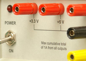
 This is a standard bench power supply for prototyping electronic circuits.
Its main feature is a selection of outputs at standard fixed voltages used in electronics. Because the outputs are fixed you do not have to worry if the voltage is correct, you just plug the wire in. It is quick and easy to use.
You will probably still need a conventional variable power supply to test circuits over a range of voltages - but this is the one that you will use for day-to-day development.
It features four fixed outputs with an overall 1 amp capacity:
- +5V and +3.3V
- +9V or +12V or +15V
- -9V or -12V or -15V
This power supply was intended to be straight forward and easy to use without controls that needed to be adjusted. It should supply all the standard voltages commonly used in electronic circuits at 500mA or more.
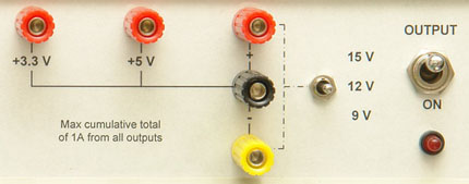 The power supply offers two fixed outputs of 3.3V and 5V, and two other voltages (plus/minus 9V, 12V or 15V) which are selected by the toggle switch.
All are referenced to the black common terminal.
The outputs are enabled by the output switch. This instantaneously disconnects the output, compared to the power switch, which, when turned off, can leave the outputs powered for some seconds due to the charge in the filter capacitors.
The circuit was designed around the LM317 and LM337 three terminal regulators. These are simple, rugged and used in many such power supplies.
The only downside is that there is no provision for current limiting... in the event of a short or something similar going wrong this power supply will attempt to drive 1.5 amps through your test circuit. Current limiting was left out because it would be difficult to properly implement and it would result in something that had to be adjusted - which was just what this project was trying to avoid.
Standard range fixed resistors are used to set the output voltages, and because of this careful attention given was to ensure that the values selected gave an result that was as close as possible to the desired voltage. In this design the maximum error due to the values of the resistors chosen is 0.89% and in most cases it is less than 0.5%. These resistors are specified as 1% tolerance and the LM317 and LM337 regulators have a tolerance of 1% also. So, the maximum error would be the sum of these (ie, 3%), but in most cases would be somewhat less. This is much better than the standard tolerance for these voltages which is 5%.
In the prototype the 3.3V output actually produced 3.299V, an error of 0.03% (close to the error of the measuring DMM). The 5V output actually produced 4.994V or an error of 0.12%.
Variable resistors could have been used to trim the output voltage to a precise value but, given the results, that would have been unnecessary and would have introduced a source of unreliability.
This schematic is also available from the download section at the end of this page.
 The circuit is reasonably conventional. The two diodes around each regulator are there to protect the regulator from unusual events such as the output being connected to a negative or higher voltage.
No specialised components are used, the voltage select switch (+/- 9/12/15V) is a center off switch with three positions. All resistors (with the exception of the current limiting resistors for the LEDs) should be 1% metal film.
The +5V and +3.3V regulators take their input from the output of the regulator which supplies the +9/12/15 volts. The reason for this is to spread the heat dissipation involved in supplying a low voltage like 3.3V across two regulators rather than one. For example, when the top regulator is set to 12V and the 3.3V regulator is supplying 1 amp both the regulators will be dissipating approx 9 watts. Whereas, if one regulator was used to supply 3.3V from the 21V supply the dissipation in that one regulator would be almost 18 watts.
The power supply was built into a small bench case with each regulator and its associated components assembled on small pieces of veroboard. The regulators were bolted onto a heatsink and the veroboard that they were attached to were simply supported by the legs of the regulators. The power supply was so simple that nothing more sophisticated than that was required.
Each regulator must be attached to a substantial heatsink. If a single heatsink is used then it should be of reasonable size as it could be called on to dissipate up to 20 watts. Typically a heatsink with less than 2.5 degrees per watt should be selected. For example, Altronics H0574 or Jaycar HH-8570. Note that insulating grommets, mica shims and heat conducting grease should be used to electrically isolate the mounting tab of each regulator from the heatsink and each other.
If separate heatsinks are used for each regulator then less than 5 degrees per watt heatsinks should be used. Also, insulating hardware is not needed if the heatsinks are electricially isolated from each other (e.g. attached to the plastic case).
The front panel was made by designing the panel in Visio and printing the output onto paper with a sticky backing that was suitable for laser printers. This printout was trimmed and stuck onto the drilled front panel. Finally a layer of clear sticky film (often used to protect book covers) was stuck over the paper and trimmed to size.


 The power supply offers two fixed outputs of 3.3V and 5V, and two other voltages (plus/minus 9V, 12V or 15V) which are selected by the toggle switch.
 The circuit is reasonably conventional. The two diodes around each regulator are there to protect the regulator from unusual events such as the output being connected to a negative or higher voltage.


